Clarifiers Efficiency of Solids Removal Related To. The angles and configurations of the plates are vastly different from manufacturer to manufacturer.
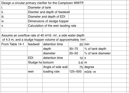
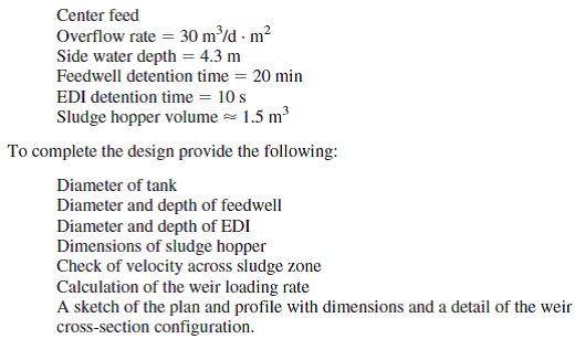
Design A Circular Primary Clarifier For The Camptown Chegg Com
Secondary Clarifier Design Fourche Creek WWTP 10 PurposeObjective Perform calculations necessary to design the new circular secondary clarifier for the Fourche Creek WWTP in Little Rock AR.

. Nominally designed to handle 125 MLd overflow w ith an equal. COMPUTER-AIDED DESIGN OF CIRCULAR CLARIFIERS Odediran ET Ayo DB. If the flow to the unit is 485 MGD what is the surface loading rate.
Depending on the textbook you reference you will see. January 2016 5-1 Design Criteria Ch. An increase above the design SLR will likely result in an increase in solids leaving the clarifier.
Ff COMPUTER-AIDED DESIGN OF CIRCULAR CLARIFIERS Odediran ET Ayo DB. In rectangular clarifiers lengthwidth ratio is between 15 and 75 usually 3. Return activated sludge recycle ratio is 1.
In circular clarifiers the radiusheight is usually between 25 and 8. 50-56 the titles Vi and TSS are reversed. 55 the underflow c.
37 Full PDFs related to this paper. But other design variables are all over the map. If a clarifier is 22 ft 3 inches long and 7 ft 7 inches wide what is the surface area in sq.
In a circular clarifier it could be up to 10. Characteristics of the Clarifier Flow Characteristics in the Clarifier Flow Must be Dispersed Evenly Throughout. Overall clarifier volume from the largest to the smallest designs can fluctuate as much as 150 or more.
This article outlines factors that are cen-tral to the design and operation ofclarifiers as well as tools available to analyze. Clarifiers form part of the process known as sedimentation. What is the volume of water in the clarifier.
Skimmer A surface skimmer consisting of a steel channel with neoprene blade attached shall be. Basin and the final clarifier Figure 1which are inseparablewith the performance ofone closely linked to that ofthe otherThe failure to consider this interdependency has led to poor clarifier design and operation. Chemical Engineering Department University of Lagos Akoka Lagos Nigeria.
Size Energy Dissipating. Design and installation of concrete grout shall be the responsibility of the installing contractor. In Table I of the July article improve Clarifier and Thickener Design and Operation by Joel Christian pp.
The result of this calculation can be compared with design. Calculate acceptable surface overflow rates 2. Circular Clarifiers SkimmerSludge Collector.
A circular clarifier has a diameter of 40 ft and a depth of water of 25 ft. Circular primary clarifiers are used to separate suspended solids from a liquid. Typically weir loading rates are.
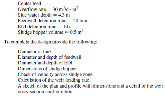
In the following table primary clarifiers design parameters values are established. Plate spacing will vary from 34 to 2 and more. Design circular secondary clarifiers for an extended aeration activated sludge system receiving a flow of 250 000 m3d average 375 000 m3d peak flow.
They are used extensively in the waste water treatment and water treatment industries but also in mining facilities reverse osmosis plants and paper and pulp plants to name a few industries. PDF On Jan 1 2009 Nikolay Stojanov Voutchkov published Clarifier Design Find read and cite all the research you need on ResearchGate. These are circular 17 m diameter by 25 m deep and centrally fed.
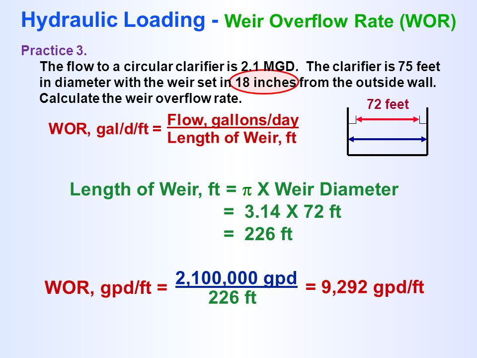
A circular clarifier has a diameter of 150 ft. Normally weir overflow rates of 10000 to 20000 gpdft are used in the design of a settling tank. Surface Area Calculations Work Calculations on Separate Paper Answers Given on Next Slides Practice 1.
Torque required to turn a rake arm would equal the resultant force of the uniform load LR R Radius of the basin multiplied by the moment. Pounds per foot applied to the rotating sludge removal arm. In the overloaded case on p.
Clarifier Bottom The bottom of the clarifier shall be grouted concrete that conforms to the dimensions shown on the drawings. The first TSS is 31 and the first Vi is 6045. The result of this calculation can be compared with design.
For secondary clarifiers that follow an activated sludge system the solids loading rate should fall in the range of 12 to 30 pounds of solids per day per square foot of clarifier surface area. Calculate minimum required surface area and clarifier diameter 3. Chemical Engineering Department University of Lagos Akoka Lagos Nigeria.
If a clarifier is 25 ft long and 9 ft wide what is the surface area in sq. Normally weir overflow rates of 10000 to 20000 gpdft 2 are used in the design of a settling tank. Calculation of torque for a circular drive unit is based on the simple cantilevered beam type of equation with a uniform load L ft.
Volume gal 0785 x. A short summary of this paper. The weir overflow rate can be determined by.
SOM - State of Michigan. 5 CHAPTER 5 Clarifiers 51 General Criteria 511 Purpose 512 Number of Units 513 Arrangements 514 Tank Configurations 515 Flow Distribution 52 Design Loading 521 Primary Clarifiers 522 Intermediate Clarifiers 523 Final Clarifiers 524 Weir Loading Rates 525 DepthDetention Time. The activated sludge system has MLSS concentration of 4160 mgl.
Circular Clarifiers

Volume And Surface Area Of A Cylinder Formulas Right Circular Cylinder Cylinder Formula Algebra Formulas Surface Area
Clarifier Calculations Ppt Download
Solved Design A Circular Clarifier For A Flow Rate Of 34 560 M3 D Chegg Com
Wastewater Clarifier Performance
Wastewater Clarifier Performance
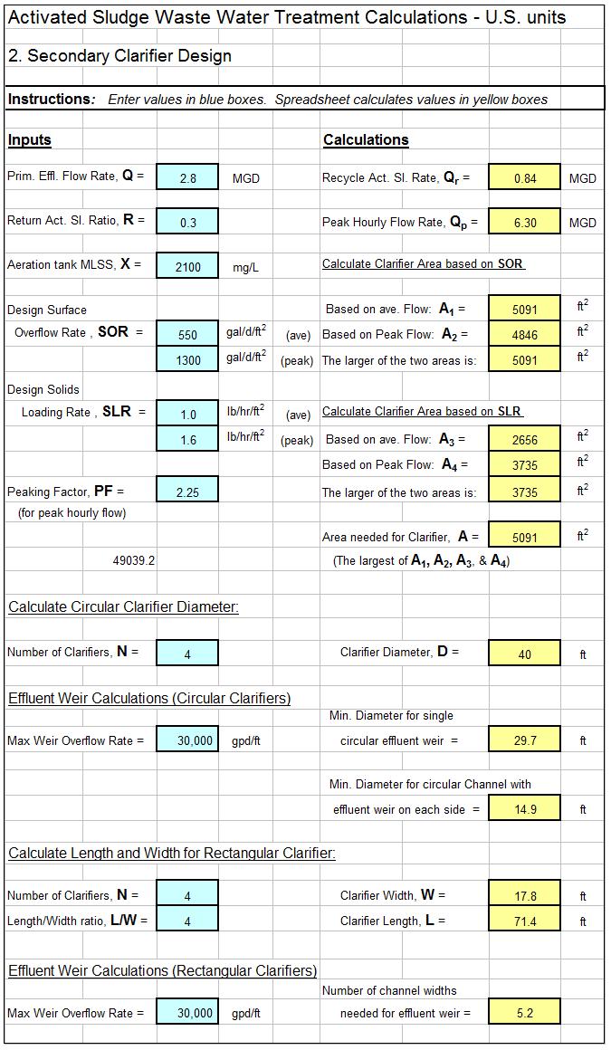
Activated Sludge Secondary Clarifier Design Spreadsheetlow Cost Easy To Use Spreadsheets For Engineering Calculations Available At Engineering Excel Spreadsheets
Solved Design A Circular Clarifier For A Flow Rate Of 8 450 M3 D Chegg Com
0 comments
Post a Comment